Cylindrical warping re-projects a photograph onto the surface of a cylinder centred on the camera. It is used to build panoramas: once every photo is on the same cylinder, neighbouring photos differ only by a horizontal shift, which is much simpler to align than a rotation.
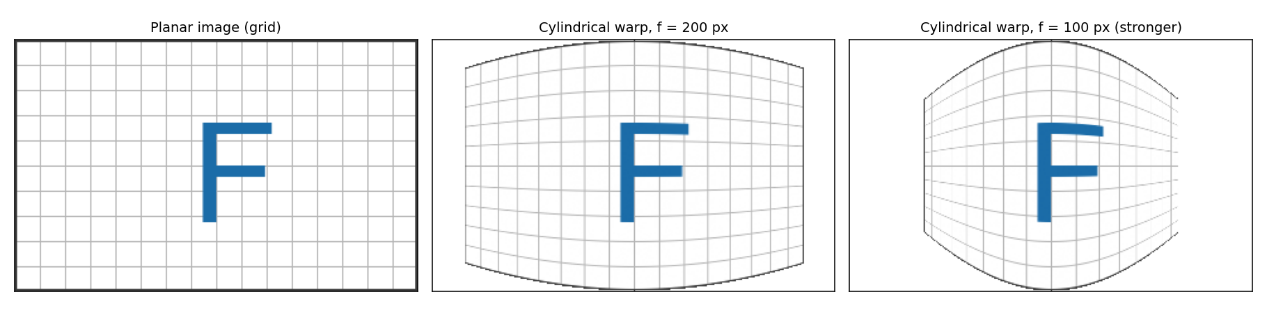
A planar image of a grid, and the same image warped onto a cylinder with two focal lengths. Vertical lines stay vertical and straight, while horizontal lines bow. A smaller focal length means a stronger effect.
Why Use a Cylinder?
A normal photo is a planar projection (a flat sensor). When a camera pans around, the projection of the same world onto several planes is related by a homography (Homographies and Perspective Warping), and a wide panorama on a single plane stretches badly at the edges.
On a cylinder, equal turns of the camera correspond to equal horizontal distances along the surface. So for a camera that rotates about its vertical axis, each new photo is a pure translation of the previous one in cylindrical coordinates. Alignment then needs only a shift (found by feature matching and robust fitting, see RANSAC) instead of a full homography per pair.
flowchart LR
    A[Photos taken while panning] --> B["Warp each onto a cylinder (needs focal length f)"]
    B --> C["Estimate the horizontal shift between neighbours"]
    C --> D[Blend overlapping regions]
    D --> E[Panorama]
The Mapping
Let be the focal length in pixels, and measure image coordinates from the image centre. A point on the image plane lies at angle around the cylinder axis and height up the cylinder:
The cylindrical image coordinates (unrolling the cylinder, with radius ) are
For warping, use the inverse mapping: for each output pixel find its source and interpolate there (Image Warping):
Behaviour of the mapping:
- Near the centre (), and : the centre is almost unchanged.
- Vertical lines stay vertical, since depends only on . Horizontal lines curve, because shrinks with .
- Edge pixels are pulled in, so the result is not rectangular and the border has to be cropped or filled.
- The mapping is non-linear, so it cannot be written as a matrix like the transformations in Image Warping.
Choosing the Focal Length
must be in pixels and should match the real camera. It can come from the camera’s calibration, from the lens’s field of view,
or from image alignment. A wrong leaves curved seams and misalignment. Wide-angle lenses with strong lens distortion should be undistorted first.
Assumptions and Limits
- The camera rotates about (nearly) its optical centre. Translating the camera adds parallax, which no warp can remove.
- The rotation axis is vertical and the camera is level, otherwise the shifts between frames are no longer pure horizontal translations.
- Covers a 360-degree horizontal sweep but limited vertical range. A spherical warp is the analogue when the camera also tilts a lot.
Code: Image Warping Snippets.
Source: Szeliski, Computer Vision: Algorithms and Applications, chapter on image stitching (cylindrical and spherical coordinates). The formulas were verified with a round-trip test in my own implementation.
Related: Computer Vision MOC, Image Warping, Homographies and Perspective Warping, Image Interpolation, Image Warping Snippets